Capacitor Esr Meter Schematic. — in this article we will build an esr meter and learn how to measure the esr of capacitor using 555 timer ic and. — in this post i have explained a simple esr meter circuit which can be used for identifying bad capacitors in an. The schematic of the esr meter is composed of design elements from various. For capacitors connected in parallel, the measurement gives the overall resistance. this article describes the construction of an analog meter for measuring the esr (equivalent series resistance) of an. — figure 2: The specific capacitors must be removed if their individual esr is to be determined. Diy examples found on the. Accurate modeling of power electronic converters, i.e., obtaining control to output transfer function, must include series resistance of capacitors and inductors. — esr tests can be performed when the capacitor is in the circuit or out of the circuit.
from circuitdigest.com
Diy examples found on the. — in this article we will build an esr meter and learn how to measure the esr of capacitor using 555 timer ic and. The schematic of the esr meter is composed of design elements from various. — esr tests can be performed when the capacitor is in the circuit or out of the circuit. Accurate modeling of power electronic converters, i.e., obtaining control to output transfer function, must include series resistance of capacitors and inductors. this article describes the construction of an analog meter for measuring the esr (equivalent series resistance) of an. For capacitors connected in parallel, the measurement gives the overall resistance. The specific capacitors must be removed if their individual esr is to be determined. — figure 2: — in this post i have explained a simple esr meter circuit which can be used for identifying bad capacitors in an.
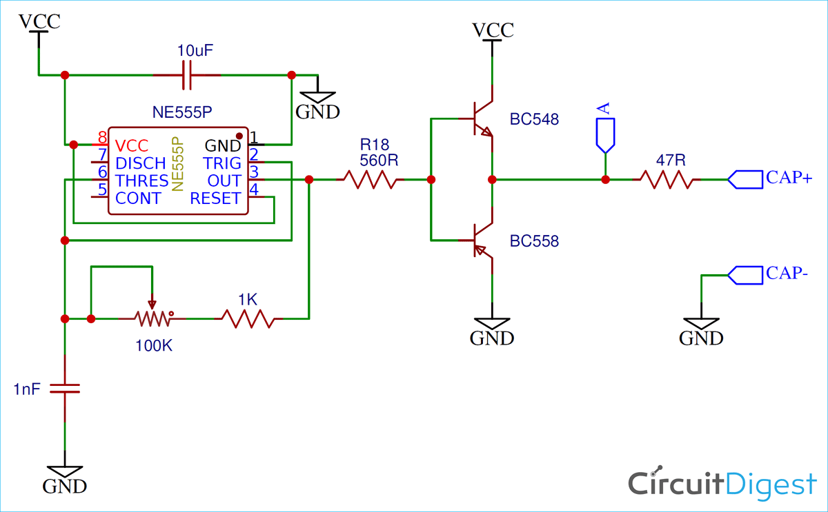
Capacitor ESR Meter Circuit Diagram using 555 Timer
Capacitor Esr Meter Schematic Accurate modeling of power electronic converters, i.e., obtaining control to output transfer function, must include series resistance of capacitors and inductors. — figure 2: Diy examples found on the. — in this post i have explained a simple esr meter circuit which can be used for identifying bad capacitors in an. this article describes the construction of an analog meter for measuring the esr (equivalent series resistance) of an. — in this article we will build an esr meter and learn how to measure the esr of capacitor using 555 timer ic and. For capacitors connected in parallel, the measurement gives the overall resistance. — esr tests can be performed when the capacitor is in the circuit or out of the circuit. Accurate modeling of power electronic converters, i.e., obtaining control to output transfer function, must include series resistance of capacitors and inductors. The schematic of the esr meter is composed of design elements from various. The specific capacitors must be removed if their individual esr is to be determined.